
Products
product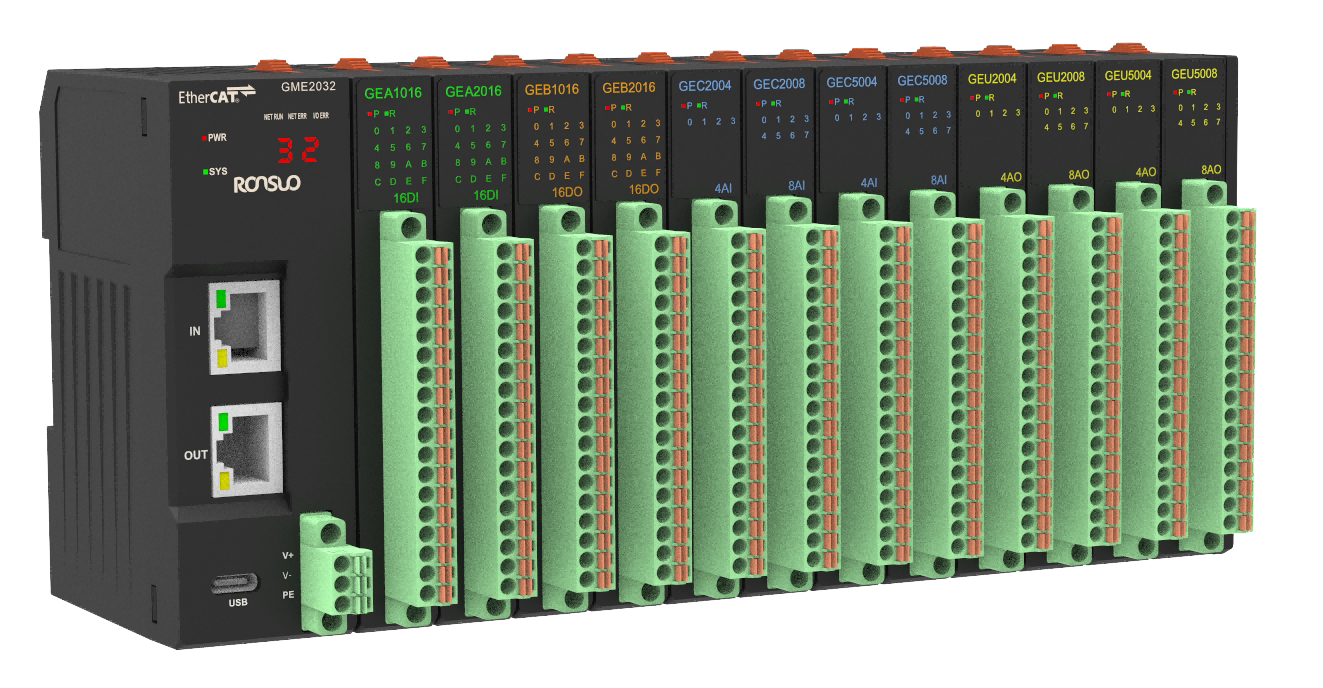
 Product Intro
The G-series card-type I/O modules adopt a modular card structure design, facilitating flexible combination and expansion. They support digital or analog signal acquisition and control, and connect to the main control system via Modbus, EtherCAT, etc. With advantages such as small size, easy installation, and hot-swappability, they are widely used in automation scenarios such as intelligent manufacturing, equipment integration, and distributed control.
 News
News
Product overview
G series card type IO module is a modular structure design equipment. The EtherCAT adapter
can be extended to access up to 32 I/O modules for real-time data communication via the
EtherCAT bus. To provide users with high-speed data output, data collection and optimization of
system configuration, simplify field wiring and improve system reliability.
EtherCAT adapter supports a wide range of expansion modules, including digital input modules, digital output modules, analog input modules and analog output modules. It can meet all kinds of industrial automation control applications.
Model description
G Series card IO module is composed of EtherCAT adapter, digital input module (DI), digital
output module (DO), analog input module (AI) and modular output module (AO). One adapter can access up to 32 expansion modules for flexible combination, as shown in the following figure:
Device model list
| No. | Type | Name | Model | Description |
|---|---|---|---|---|
| 1 | Adaptor | Adaptor module | GME2032 | EtherCATadaptor, support up to 32expansion modules |
| 2 | DI module | DIexpansion module | GEA1016 | 16-channlsDIexpansion module, NPNinput |
| 3 | GEA2016 | 16-channlsDIexpansion module, PNPinput | ||
| 4 | DO module | DOexpansion module | GEB1016 | 16-channlsDOexpansion module, NPNoutput |
| 5 | GEB2016 | 16-channlsDOexpansion module, PNPoutput | ||
| 6 | AI module | AIexpansion module | GEC2004 | 4-channlsAIexpansion module, 0~10Vinput |
| 7 | GEC2008 | 8-channlsAIexpansion module, 0~10Vinput | ||
| 8 | GEC5004 | 4-channlsAIexpansion module, 4~20mAinput | ||
| 9 | GEC5008 | 8-channlsAIexpansion module, 4~20mAinput | ||
| 10 | AO module | AOexpansion module | GEU2004 | 4-channlsAOexpansion module, 0~10Voutput |
| 11 | GEU2008 | 8-channlsAOexpansion module, 0~10Voutput | ||
| 12 | GEU5004 | 4-channlsAOexpansion module, 4~20mA output | ||
| 13 | GEU5008 | 8-channlsAOexpansion module, 4~20mA output |
Product features
Product features
⚫ The adapter supports flexible combination with various types of I/O modules
⚫ One adapter supports up to 32 extended I/O modules
⚫ Support flexible expansion, and can expand digital and analog modules, applicable to various
industrial control scenarios
⚫ The adapter communication port complies with standard Industrial Ethernet EtherCAT protocol communication
⚫ The channel indicator on the module is displayed for easy viewing of the channel status
⚫ Module ports are screw-free spring terminals, convenient construction and maintenance
Technical Parameters
Module general parameters
| Module general technical parameters | ||
|---|---|---|
| Item | Parameters | |
| Size | EtherCAT adapter | 34mm*70.95mm*100mm (W*D*H) |
| I/O expansion module | 15.6mm*70.95mm*100mm (W*D*H) | |
| Weight | EtherCAT adapter | 110g |
| I/O expansion module | 90g | |
| Wiring mode | EtherCAT adapter | Spring terminal (no screws) |
| I/O expansion module | Spring terminal (no screws) | |
| Working environment | Working temperature | -20℃~85℃ |
| Storage temperature | -20℃~105℃ | |
| Relative humidity | 10~95%RH, no condensation | |
| Protection class | Protection | IP20 |
| Surge protection | EtherCAT adaptor | Power input port 2kV |
| I/O expansion module | DI/DO power input port2kV | |
EhterCAT adaptor parameters
| EtherCAT adaptor technical parameters | ||
|---|---|---|
| Item | Parameters | |
| Module power supply | Wiring mode | 3PSpring terminal (no screws) |
| Working voltage | 24VDC (12~36V) | |
| Working current | 650mA | |
| Power protection | Anti-reverse protection | |
| Protocol type | EtherCAT | |
| Communication port | RJ45x2 (IN, OUT) | |
| The number of extensible modules | 32 | |
| Input/ output maximum bytes | 1024 Byte |
| Cable requirements | cat5 or higher shielded network cables |
| Transmission rate | 100Mbps |
| Transmission distance | ≤100m |
| Firmware upgrade and debugging | TYPE-C port |
Digital input module (DI) parameters
| Digital input module (DI) parameters | ||
|---|---|---|
| Item | Parameter | |
| Module power supply | Wiring mode | 18P springterminal (no screws), power occupies 2P |
| Working voltage | 24VDC (12~36V) | |
| Power protection | Anti-reverse protection | |
| Input connection mode | 18P springterminal (no screws), input occupies 16P | |
| Number of input channels | 16 | |
| Signal type | NPN/PNP | |
| Module power consumption | 0.2W | |
| Input current | <1mA/Channel | |
| Signal voltage -0 | <4VDC | |
| Signal voltage -1 | >6VDC | |
| Input filtering | Default: 5ms (range 1~100ms) | |
| Isolation mode | Optocoupler isolation | |
| Isolated withstand voltage | 500V | |
| Input status display | The green light is on when the signal is active | |
Digital output module (DO) parameters
| Digital output module (DO) parameters | ||
|---|---|---|
| Item | Parameters | |
| Module power supply | Wiring mode | 18P springterminal (no screws), power occupies 2P |
| Working voltage | 24VDC (12~36V) | |
| Power protection | Anti-reverse protection | |
| Input connection mode | 18P springterminal (no screws), input occupies 16P | |
| Number of input channels | 16 | |
| Signal type | NPN/PNP | |
| Module power consumption | 0.3W | |
| Load type | Resistive load/ inductive load | |
| Output current | 0.5A/Channel,4A/Module | |
| Output protection | Output short-circuit protection | |
| Isolation mode | Optocoupler isolation | |
| Isolated withstand voltage | 500V | |
| Output status display | The green light is on when the signal is active | |
Analog input module (AI) parameters
| Analog input module (AI) parameters | |
|---|---|
| Item | Parameters |
| Input connection mode | 18P springterminal (no screws), input occupies 16P |
| Number of input channels | 4, 8 |
| Module power consumption | 0.3W |
| Input signal type (voltage type) | 0~10V |
| Input signal type (current type) | 4~20mA |
| Input current | <1.5mA/Channel |
| Input impedance (voltage type) | >500KΩ |
| Input impedance | 250Ω |
| Resolution | 16bit |
| Sampling rate | 1Ksps |
| Precision | 0.05% |
| Isolated withstand voltage | 500V |
| Input status display | The green light is on when the signal is active |
Analog output module (AO) parameters
| Analog output module (AO) parameters | |
|---|---|
| Item | Parameters |
| Output connection mode | 18P spring terminal (no screws), output occupies 16P |
| Number of output channels | 4, 8 |
| Module power consumption | 0.5W |
| Output signal type (voltage type) | 0~10V |
| Output signal type (current type) | 4~20mA |
| Output impedance (voltage type) | >500Ω |
| Output impedance (current type) | <600Ω |
| Resolution | 16bit |
| Precision | 0.1% |
| Output protection | Output short-circuit protection |
| Isolated withstand voltage | 500V |
| Output status display | The green light is on when the signal is active |
Common faults
During device use, some faults may occur, and the user can restore the normal operation of the
device according to the faults and solutions listed below. If the problem cannot be solved, please contact our company.
Power failure
Fault: the panel indicator lights are not lit after power-on.
Solution:
1. Check whether the power cable is connected and is in good contact with the terminal.
2. Check whether the positive and negative poles of the power cable are reversed.
3. Use a multi-meter to measure whether the input voltage is in the specified voltage range
(12~36VDC).
Communication failure
Fault: EtherCAT communication failure
Solution:
1. Check whether the device parameters are configured correctly.
2. Check whether the communication wiring is correct (Note whether the RJ45 ports are
properly connected IN and OUT)
3. Check whether the <xxx.xml> file has been correctly imported into the upper computer.
4. Check whether the device node address is correctly written.
5. Check whether the system restarts after the configuration is complete.
Messages
News

Email: 616526410@qq.com

Hotline: 13609016130

Address: Room 314, 3rd Floor, No. 9, Kemulang South Road, Tianhe District, Guangzhou

Filing No.: 粤ICP备2023092377号-3
Products
 Temperature controller Temperature acquisition device Industrial I/O Modules Industrial gateway Power Regulator
 Solutions
Semiconductor/Chip Industry New energy/energy storage industry Optoelectronics/Display Industry Rubber/Plastics Industry Biopharmaceutical industry Industrial Furnaces/Thermal Industry Mechanical Automation Industry Other integrated applications Support
Manuals
Tutorials
Tools
News
Company News Exhibition News Media Information


 Location:
  Products


